SLR Specifications
SLR systems aren't all the same and the SGF uses particular methods and equipment to perform the necessary tasks.
The key components of a laser ranging system are the fast pulsed laser, the accurate counter or timer, the stable precise tracking telescope, the detector and a software package to drive the system. There are many other essential parts that are also detailed below and enable successful satellite tracking.
These are the solutions in operation at the SGF. They are not the only options and other SLR stations may well do things differently.
Lasers
The SGF has two lasers for laser ranging. The first is a Nd:YAG crystal solid-state laser that generates infrared light, which is frequency doubled to give green laser light with a wavelength of 532 nanometres. The laser fires in short pulses 100 picoseconds in duration. Each pulse has energy of approximately 20 millijoules and the laser fires at a rate of 12 pulses per second.The second laser was manufactured by High-Q lasers and generates light at approximately the same wavelength (532nm) but in far shorter and less energetic pulses, 10ps wide and 0.4mJ. However, this second laser fires more rapidly at 2000 times per second.
The observer is free to choose which laser to use depending on sky conditions and the difficulty of tracking the particular target. This is achieved by having the second laser positioned at 90 degrees to the first, so that a selecting switch can move a mirror in to position to direct the chosen beam to the telescope. The laser switch takes less than 30 seconds.
Epoch timer
The SGF uses an event epoch timer built from modules from Thales Systems, two timing modules and a clock module. When interrogated by the system PC, the timer returns its current time to a precision of a few picoseconds, which is then associated with either a laser fire or return signal detection event. The epoch timer allows multiple laser shots to be in flight at a time, essential for 2kHz laser ranging.The modules take 1-pulse per second and 1kHz signal inputs. The start and stop epochs are matched in real-time in software so that the resulting differences give range measurements.
A 1-pps is applied to both timing modules to allow epoch synchronisation. This is supplied from the active hydrogen maser frequency clock in operation at the SGF. 1-kHz pulses are also used to determine the offsets between the modules and the timer takes control inputs from the system PC.
Telescope
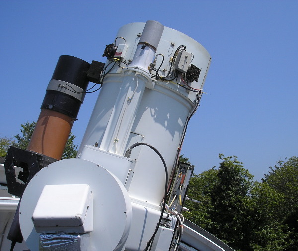
The SGF telescope has a wide aperature, it is compact, agile and precise. It has to collect enough light from faint signals reflected from satellites thousands of kilometres away and must be able to move quickly and maintain precise pointing as the satellites move across the sky.It is a reflective Cassegrain design with a 50cm aperture. It can point accurately to an object in the sky to 1-2 arcseconds (1 arcsec = 1/3600 of a degree) and can slew at more than 5 degrees per second whilst able to maintain pointing to within a few arcseconds.
Mounted on the side of the telescope is a smaller telescope through which the laser is emitted.
Detector
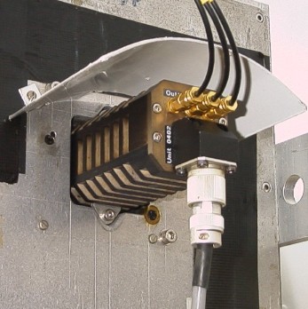
If more than a single photon reaches the SPAD 'at the same time' significant bias in the range measurement can result. This lead to the development, at the Czech Technical University and the Technical University of Graz, Austria, of a detector incorporating an automatic time-walk compensation unit, C-SPAD.
The SGF currently uses a SPAD designed for kHz laser ranging which has reduced self generated 'dark' current noise and reduced error when gating closer than 100ns. The SGF works strictly at a single-photon level of return. Theoretical and experimental considerations lead to the conclusion that significant and essentially un-measurable range bias can result when high levels of return are obtained from extended satellite reflector arrays, which include those of all the principle geodetic satellites.
Software and Networking
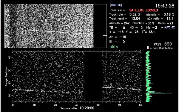
A large part of the work to run a SLR system is done in software. This includes the controlling of the laser, detector, radar, telescope and timer and other devices. The satellite predictions used at the SGF are in the standard CPF format and are used to fit a high order polynomial which allows quick reference and direction for the telescope without rereading buffers or interpolating.Epoch matching is performed in software by identifying laser 'starts' and detector 'stops' with the correct delay difference. This data is then transferred by TCP-IP to a secondary PC which writes the data to a file and sends it to the display software, which detects satellite track in real-time. A program is later used once the satellite pass is over to extract the data and form 'normal points' for submission to the ILRS.
Other SLR system components
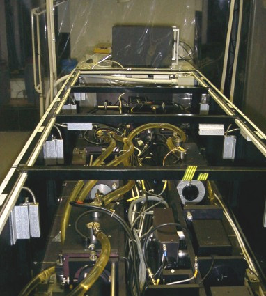
Optical
When the laser fires, the light triggers a 'start' diode which produces an electrical signal to go to the epoch timer. The laser pulse is reflected off a series of flat mirrors at 45 degrees, called the coudé path, and is emitted at the side of the telescope. The divergence of the laser beam is minimised in the laser bed to give a sharp, near parallel beam, but this can be adjusted at teh emitter to spread the beam for SLR tracking of fast, low altitude satellites. It is necessary to align the beam so that it travels in parallel to the maintelescope adn this is done by steering the final flat mirror which is mounted on piezoelectric crystals that tilt the mirror according to the applied voltages.
The returning signal is collected by the telescope and focussed on to the detector. In the path are a number of different types of filters. The first is the dichroic filter which allows 99% of the green light to transmit but reflects other wavelengths, at night this allows stars, a sunlit satellite and the outgoing pulse to be seen in a low-light camera. A narrowband filter is positioned in front of the detector to filter out all wavelengths, except 532nm ± 0.1nm, with a transmission efficiency of approximately 25%. This filter is contained in an oven and held at constant temperature, which can be tuned to match the exact wavelength of the laser. This enables daytime SLR as only the laser light reaches the detector. Finally a graded neutral density wheel is placed before the detector which rotates during a pass according to the signal intensity at the detector, keeping to single-photon levels.
Electronic
Much of the SLR central control is performed via the range gate generator, developed at the Austrian Academy of Sciences, Space Research Institute, Graz. This unit fires the laser and manages a register of epochs when the detector should be armed. At high repetition rates, such as with the SGF 2kHz laser, many pulses are in flight at any one time.The radar safety system in place at the SGF tracks with the telescope and emits microwave radiation. It listens for echos from this broadcast and is able to detect approaching aeroplanes. A detection signal is sent straight to a pockels cell in the laser which is imrmediately closed.