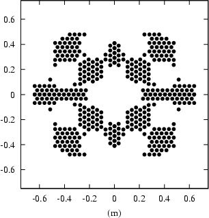
See
ccr-pos.txt file
for arrangement data (unit: mm) of the quarter of the whole array.
The origin ( 0, 0 ) is the centre of the flat array.
If the first item is marked 's', the reflector is located on the
border with any of other quarters. The ( x, y ) coordinate system
follows the ( x, y, z ) of Fliegel (JGR, 1992),
that is, the y-axis is along the solar panel and
the xy-plane faces the geocentre.
This plot shows the arrangement of 396 ccrs. The size is over 1 m x 1 m square. The gaps are considered to be filled by antennas. However, for laser ranging, no ccrs are obscured by any objects according to V. Vasiliev. The reflection point of the array centre is at 1.51 m distance along the geocentre direction from the satellite centre-of-mass.

Every ccr will equally respond all the time because the angle of incidence of the laser pulse is the same for all ccrs. This fact is totally different (actually reduces our work) from other ordinary satellites in which the intensity from each ccr must be independently calculated with respect to the angle of incidence. At the same time, this causes quite a long rise time which is new to us.
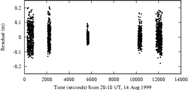
Some stations have experienced variation of the full-rate scattering even during a pass. This figure shows the residual distribution of a pass observed at a single-photon station of Herstmonceux 7840; started at 35-deg elevation, topped at 76-deg and ended at 40-deg. Obviously the scatter gets larger at lower elevation. This is because the angle relative to the satellite nadir is wide when the satellite is at low elevation from a station. The nadir angle is zero when the satellite is at the zenith, but it amounts to 13.7 degrees when at 20-deg elevation. Even if the transmitted laser pulse has a short width, the retro-reflected pulse will spread nearly 30 cm due to this effect.

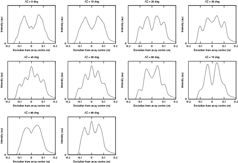
The retro-reflection is expected to vary with respect to the azimuthal angle to the ccr array. The satellite signature effect was simulated. The satellite is assumed to be at 30-deg elevation and the system noise of Herstmonceux (approx 1 cm rms, skewed) was convolved. Assuming that the horizontal direction in the ccr arrangement graph equals zero degrees azimuth, the responses were simulated every 10 degrees. The pulse shape changes dramatically as shown below. The long leading edge, up to 15 cm, is very new to our signature study because we have only experienced the satellite response with a sharp leading edge even in cases of large satellites like Ajisai and Topex. It is also very challenging to laser ranging systems, especially multi-photon systems whose detection timing of arrival is "somewhere" between the first photon and the centroid. On the other hand, single-photon systems always refer the centroid although its full-rate scattering is generally large.

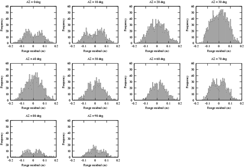
The azimuth can be computed from the position of a satellite, a station and the sun, at the observation time. We used Herstmonceux full-rate residual data, choosing only 30 to 40 degrees of elevation and sorting by the azimuthal angle of incidence.
Each of the graphs below should be compared with each of those above. The agreement between the twos are not very precise, but they roughly match in terms of the number of peaks (one or two) and the scattering size.

The variation of the pulse shape/spread is not a problem for single-photon systems, but it has probably degraded the accuracy of multi-photon systems. We need to model the centre-of-mass correction dependent on the satellite orientation and the laser system's policy.
Lastly, it should be stressed that the large array enabled us to obtain a large amount of laser range data (3 times of GPS) though such a satellite signature problem is contingent to the array size.