Thanks to V. Vasiliev (Russian Institute of Space Device Engineering) and H. Kunimori (ILRS Misson WG Coordinator; CRL, Japan), we have obtained the basic positional data for the corner cube reflectors (ccr) on the two Etalon satellites. In compiling this note we have also used the information contained in the paper `ETALON-1, -2 Centre of Mass Correction and Array Reflectivity', by Mironov, Emetz, Zaharov and Tchebotarev, published in the Proceedings of the Eighth Int. Workshop on LR Instrumentation, held in Annapolis, MD, in 1992.
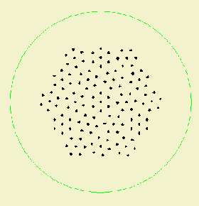
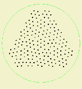
We were given the coordinates of the two basic structures from which the array system is built; the 'Type-A' element of 133 individual ccrs, and the 'Type-B' element of 175 ccrs, as shown in the following two plots.


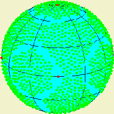
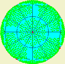
The array system is built from six Type-A elements, and eight Type-B elements, and we were also provided with the coordinates on the spherical satellite that mark the centres of each of these 14 elements. The Type-A elements occupy the polar and equatorial regions, the Type-B elements the mid-latitude regions of the satellite. An additional complication is that in each of the four Type-B elements in the 'southern' hemisphere of the satellite two adjacent goups of 7 ccrs are removed to leave space for the devices used to attach during launch the two GLONASS satellites that shared launches with each ETALON satellite. Thus the number of ccrs in 'northern' hemisphere Type-B elements is 175 and in the 'southern' hemisphere the number is 161. In addition there are six germanium ccrs on the satellite; one at each pole, replacing the central ccr in the appropriate Type-A element, plus four uniformly distributed around the satellite's equator. Thus the total number of ccrs on each satellite is 6*133 + 4*175 + 4*161 + 4 = 2146, of which 2140 are of fused silica and six are made of germanium.
From this information it is possible to determine the latitude and longitude of each of the ccrs in a satellite-centred reference system; the in-orbit orientation of the satellite is not known. The coordinates of each of the ccrs is given in the lonlat.eta file, where the information is a sequence number in each element (=999. for a germanium ccr) and longitude and latitude of the cube in degrees. The front face of each cube is at a distance of 641.5mm from the centre of the satellite, being recessed by 5.5mm below the surface of the satellite which has radius 647mm.
The pictures show the well-known appearance of the satellite using these derived ccr coordinates, where the fused silica ccrs are shown in green and the Germanium ones in red. The right-hand picture shows the gaps in the distribution of ccrs in the 'southern' hemisphere where the attachments, discused above, are placed.


We now plan to derive response functions for the satellites in order to estimate system-dependent CoM values.
Back to Signal Processing WG Page.
G M Appleby (gapp@nerc.ac.uk) and T Otsubo (to@nerc.ac.uk), 20 June 2000